If you are pushing for higher horsepower or dialing in a precision build, you have likely encountered the silent performance killer known as exhaust backpressure. Mastering effective turbocharger backpressure reduction strategies is essential for anyone looking to optimize their engine's efficiency and unlock the full potential of their forced induction system. When exhaust gas is trapped or restricted, it creates a bottleneck that limits turbine speed, increases combustion chamber temperatures, and significantly hinders the engine's ability to breathe at high RPMs.
In this guide, we break down the complex relationship between mechanical design, thermal management, and precision tuning. You will learn how to evaluate your current setup, from selecting the right piping diameters to leveraging advanced diagnostic tools for monitoring turbine inlet pressure. Whether you are aiming for a street-legal performance upgrade or a dedicated track machine, understanding how to manage exhaust flow is key to achieving consistent power gains and long-term reliability. By focusing on performance exhaust flow dynamics, you can ensure your turbocharger spools faster and breathes easier under heavy load.
1. Mechanical and Design Strategies for Turbocharger Backpressure Reduction
1.1 Analyzing Exhaust Geometry and Flow Dynamics
1.1.1 Selecting Optimal Pipe Diameter for Horsepower Targets
Achieving the right balance in your exhaust system begins with selecting the correct diameter. If your piping is too small, you create an unnecessary bottleneck that chokes the engine and increases turbine inlet pressure. Conversely, overly large piping can reduce exhaust gas velocity, which hurts turbo spool-up. For most forced induction builds, you should aim for a diameter that supports your specific horsepower goals without sacrificing gas speed. Proper performance exhaust flow dynamics rely on maintaining a laminar flow that allows the turbocharger to operate efficiently across the entire RPM range.
1.1.2 Evaluating Merge Collectors and Transition Smoothness
The design of your exhaust manifold or header collector is critical in managing pressure. Abrupt transitions or sharp angles cause turbulence, which significantly increases backpressure and hinders the scavenging effect. Using a high-quality merge collector that blends exhaust pulses smoothly helps streamline flow into the turbine housing. By focusing on transition smoothness, you can prevent stagnant pressure zones and ensure that each cylinder's exhaust pulse arrives at the turbine wheel with maximum kinetic energy.
1.1.3 The Impact of Mandrel Bending and Plumbing Routing
Plumbing layout is often the silent killer of turbo performance. Every crush bend in your piping creates a restriction that disrupts flow. Mandrel bending is essential because it maintains a consistent internal diameter throughout the entire curve of the pipe. Furthermore, keeping your routing as short and direct as possible reduces the distance exhaust gases must travel, which in turn lowers thermal loss and pressure buildup. A well-planned routing strategy minimizes friction losses and allows for much faster turbo responsiveness.
1.2 Optimizing Turbine Housing and Wastegate Configurations
1.2.1 Balancing A/R Ratios for Spool Characteristics versus Top-End Flow
The Area/Radius (A/R) ratio of your turbine housing dictates how the turbocharger handles exhaust energy. A smaller A/R ratio increases gas velocity for a quicker spool, but it can reach a saturation point where it becomes a restriction at high RPM. If you find your backpressure rising sharply as you approach your power band's ceiling, you may need a larger housing to allow for better top-end flow. Balancing these characteristics is a compromise that must be tailored to your specific displacement and intended usage.
1.2.2 Advantages of External Wastegates for High-Flow Pressure Relief
Internal wastegates are often insufficient for high-horsepower builds because they struggle to bypass enough volume when the turbo is pushed to its limits. An external wastegate provides a dedicated path for excess gas to exit, significantly reducing pressure buildup in the manifold. By installing a larger external wastegate, you gain precise control over boost levels and effectively vent the pressure that would otherwise force the engine to work harder during the exhaust stroke.
1.2.3 Mitigating Pressure Spikes Through Strategic Wastegate Porting
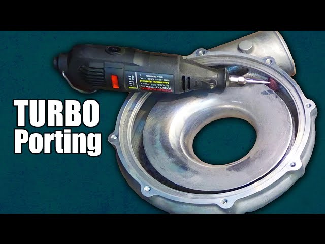
If you must use an internal wastegate setup, porting the wastegate orifice is a common method to mitigate pressure spikes. By opening up the passage, you allow for a greater volume of gas to bypass the turbine wheel. This mechanical intervention helps prevent "boost creep," where the pressure exceeds your target because the system cannot move the volume of air fast enough. Proper porting ensures that the actuator can effectively manage the turbo's speed, keeping backpressure within safe operating limits.
1.3 Thermal Management and Velocity Preservation
1.3.1 Utilizing Ceramic Coatings to Maintain Exhaust Gas Density
Exhaust gases expand as they cool, which lowers their velocity and increases density, potentially clogging the flow path. Applying ceramic coatings to the interior and exterior of your exhaust manifold and turbine housing serves as an insulator. By keeping the thermal energy inside the pipe, you maintain a higher gas velocity, which effectively reduces the resistance the turbo sees. This is a highly efficient way to manage heat without adding significant weight or bulk to your engine bay.
1.3.2 Benefits of Exhaust Wraps for Sustaining Gas Velocity
Exhaust wraps provide a cost-effective alternative to professional ceramic coating. By wrapping your manifolds and downpipe, you trap heat, ensuring that the exhaust gas retains its kinetic energy until it hits the turbine wheel. When the gas stays hot and fast, the turbo spools more readily and operates with less restriction. However, ensure that the materials used are high-quality to avoid premature degradation, as consistent heat retention is vital for sustained performance.
1.3.3 Managing Heat Soak in High-Backpressure Environments
High-backpressure environments often lead to extreme heat soak, where components surrounding the exhaust system absorb excess thermal energy. This can degrade the performance of nearby sensors and intake components. Beyond just wrapping pipes, effective heat management requires strategic placement of heat shields and ensuring there is adequate airflow within the engine bay. Managing this heat prevents the intake charge from becoming too hot, which helps maintain the overall efficiency of the forced induction system under heavy load.
2. Advanced Tuning, Diagnostic, and Measurement Techniques
2.1 Instrumenting and Monitoring Turbine Inlet Pressure
To truly understand how your turbocharger backpressure reduction strategies are performing, you must move beyond seat-of-the-pants testing and rely on hard data. The most critical metric is Turbine Inlet Pressure (TIP), which tells you exactly how much restriction exists between the engine exhaust ports and the turbine wheel. If your TIP consistently exceeds your intake manifold boost pressure by a significant margin, you are likely losing efficiency and risking engine longevity.
2.1.1 Choosing the Correct Pressure Transducers and Sensors
Selecting the right hardware is essential for accuracy. You need a dedicated, high-temperature pressure transducer capable of withstanding the extreme heat found at the exhaust manifold. Avoid using standard intake MAP sensors, as they are not calibrated for the thermal loads or the chemical composition of exhaust gases. Opt for a sensor with a stainless-steel body and a remote pigtail connection to keep the electronics shielded from the heat source.
2.1.2 Installing Dedicated Ports for Real-Time Backpressure Data
Installation requires a dedicated bung welded into the collector area of your exhaust manifold, as close to the turbine inlet as possible. Using a long, coiled stainless steel tube (often called a "pigtail") between the manifold and the sensor is a best practice. This creates a cooling buffer, ensuring that the hot exhaust gas pulses do not melt the sensor diaphragm, allowing for stable, real-time logging of backpressure levels during wide-open throttle pulls.
2.1.3 Establishing a Baseline for Turbine Inlet versus Manifold Pressure
Once your instrumentation is live, you must establish a baseline. A healthy, high-performance turbo system typically aims for a 1:1 ratio between manifold boost and turbine inlet pressure. If you see TIP reaching twice your boost pressure, your exhaust manifold is likely acting as a bottleneck. Use this data to correlate your performance exhaust flow dynamics with real-world pressure drops.
2.2 Calibration Adjustments to Compensate for Backpressure
When mechanical changes reach their limit, ECU calibration becomes your primary tool for managing high backpressure. High exhaust pressure increases the internal cylinder temperature, which dramatically raises the risk of knock. You must tune with a margin of safety that accounts for the fact that high backpressure effectively traps more residual gas in the combustion chamber during the exhaust stroke.
2.2.1 Modifying Ignition Timing to Prevent High-Load Detonation
As backpressure rises, the effective compression ratio of the engine increases because more exhaust gas is trapped in the cylinder. This creates a prime environment for pre-ignition. To compensate, tuners often pull several degrees of timing from the high-load/high-RPM ignition map. This delay prevents the combustion event from peaking too early, protecting your pistons from the stress of excessive heat and pressure.
2.2.2 Fine-Tuning Air-Fuel Ratios to Manage Exhaust Gas Temperatures
Exhaust Gas Temperature (EGT) management is vital when you are fighting high backpressure. Running a slightly richer air-fuel ratio—often shifting toward the mid-11s on gasoline—acts as an internal cooling mechanism. The extra fuel absorbs heat as it vaporizes, helping to stabilize the cylinder environment. However, monitor your EGTs closely; if they continue to climb, it is a clear indicator that you need further exhaust system flow improvements rather than just a tune-based workaround.
2.2.3 Implementing Boost Control Strategies to Limit Pressure Surges
Your boost control strategy should work in tandem with your physical wastegate setup. By implementing a sophisticated electronic boost control solenoid, you can program the ECU to "target" backpressure limits. If the sensor detects a dangerous spike in TIP, the ECU can be programmed to lower the duty cycle, venting more exhaust through the wastegate to prevent the turbo from entering an over-speed condition that could lead to catastrophic failure.
2.3 Troubleshooting Engine System Interactions
Sometimes, the issues appearing as high backpressure are actually symptoms of deeper mechanical conflicts within the engine's breathing cycle.
2.3.1 Identifying Camshaft Overlap Issues Under High Pressure
Excessive exhaust backpressure can wreak havoc on engines with aggressive camshaft profiles featuring significant valve overlap. If the pressure in the exhaust manifold is higher than the pressure in the intake manifold while both valves are open, exhaust gas will be forced into the intake port—a phenomenon known as exhaust reversion. This ruins combustion quality and lowers overall power output, regardless of how much boost you run.
2.3.2 Assessing the Impact of Restrictive Catalytic Converters
If you are utilizing a catalytic converter, it is often the single most significant source of restriction in a forced-induction system. Even high-flow metallic-core converters can reach a saturation point. If you suspect your cat is limiting performance, consider a temporary test pipe during dyno sessions to see if the drop in backpressure results in immediate gains in spool and top-end power.
2.3.3 Evaluating Forced Induction Limitations on Specific Displacement Engines
Finally, remember that every turbocharger has a "choke point" where it simply cannot move more air through the turbine wheel. If you have optimized your piping and manifold but still see high backpressure, you may have reached the physical limit of the turbine housing. At this point, the only way to reduce backpressure is to step up to a larger turbine wheel or a housing with a more aggressive A/R ratio to accommodate the mass flow requirements of your displacement.
Mastering turbocharger backpressure reduction strategies is a balancing act between raw performance gains and mechanical reliability. By systematically optimizing your exhaust manifold design, managing thermal energy to maintain gas velocity, and utilizing precision data to guide your ECU calibration, you can unlock the full potential of your forced induction system. Remember that reducing backpressure is rarely about installing the largest possible components; it is about finding the optimal flow dynamics that support your specific horsepower goals without sacrificing essential spool characteristics or engine longevity.
As you refine your setup, it is vital to keep real-world application in mind. Whether you are building a dedicated track car or a high-performance street vehicle, consistent monitoring of your turbine inlet pressure will provide the insights necessary to troubleshoot restrictive points effectively. If you want to dive deeper into the technical nuances of how these modifications impact your engine's internal efficiency, check out our guide on performance exhaust flow dynamics to better understand the fluid mechanics at play. By combining rigorous data collection with thoughtful hardware selection, you will ensure your engine breathes freely, runs cooler, and delivers power consistently across the entire RPM range.