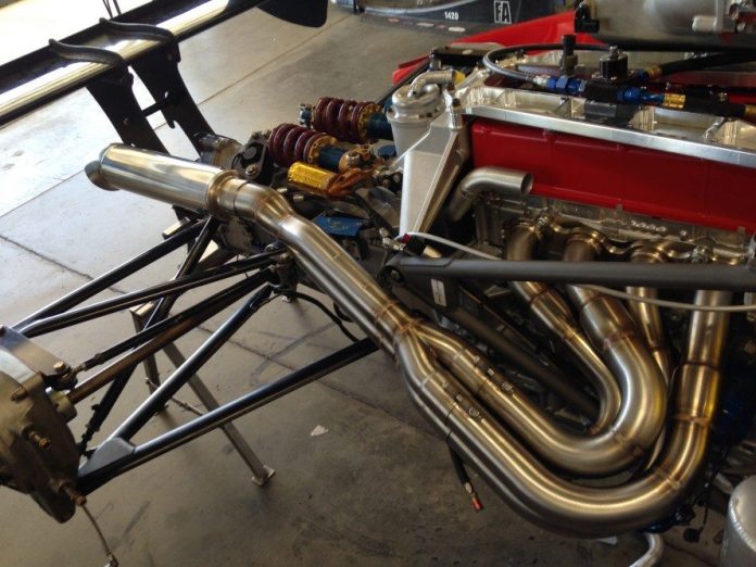
Achieving peak engine performance is rarely about simply installing the largest exhaust components you can find; instead, it requires a precise balance of fluid dynamics and timing. Automotive exhaust gas velocity optimization is the critical process of tuning your system to maintain the ideal speed of spent gases as they exit the combustion chamber. When optimized correctly, this speed promotes efficient cylinder scavenging, which draws in a fresh, dense air-fuel charge more effectively to boost power and torque. However, get the pipe diameters or routing wrong, and you risk losing that essential energy, leading to poor throttle response and an uneven power band.
In this guide, we will break down the complex relationship between pulse tuning, thermal management, and system architecture. Whether you are looking to refine your low-RPM torque for street driving or maximize top-end power for track use, understanding how to manage exhaust gas velocity vs torque mapping will help you build a more responsive, efficient, and powerful machine.
1. Engineering Principles of Automotive Exhaust Gas Velocity Optimization
1.1 Fluid Dynamics and Flow Characteristics
1.1.1 Laminar versus Turbulent Flow in Exhaust Tubing
The primary goal of an efficient exhaust system is to maintain high-velocity flow while minimizing resistance. In an ideal scenario, the exhaust gas moves in a laminar fashion, where fluid particles travel in parallel layers with minimal mixing. However, automotive exhaust is inherently chaotic. As gases encounter bends, weld points, or diameter transitions, the flow becomes turbulent. This turbulence creates localized high-pressure zones that impede the exit speed of subsequent exhaust pulses. Engineers prioritize smooth, unobstructed internal paths to keep flow as close to laminar as possible, ensuring that the engine does not work harder than necessary to evacuate combustion byproducts.
1.1.2 The Role of Bernoulli Principle and Venturi Effects
The Bernoulli Principle states that as the speed of a fluid increases, its static pressure decreases. In exhaust design, this is leveraged through the Venturi effect. By carefully tapering sections of the piping, we can increase the velocity of the gas as it passes through a constriction. This drop in pressure can be utilized to help draw the next pulse of exhaust from the cylinder head, effectively pulling the gas out rather than simply relying on the piston's upward stroke to push it. Properly calculated pipe geometry is essential here; if the diameter is too large, velocity drops and the Venturi effect vanishes, leading to stagnant gas.
1.1.3 Impact of Exhaust Temperature on Gas Density and Flow Rate
Exhaust temperature is a critical variable in velocity calculations. Heat keeps the exhaust gas energized and less dense. As gases cool, they contract, causing a significant loss in flow velocity. To maintain peak performance, thermal energy must be preserved within the tubing. This is why high-performance systems often utilize specialized materials or thermal coatings that act as insulation, keeping the gas hot and moving rapidly toward the tailpipe.
1.2 Pulse Tuning and Scavenging Mechanics
1.2.1 How Pressure Waves Facilitate Cylinder Evacuation
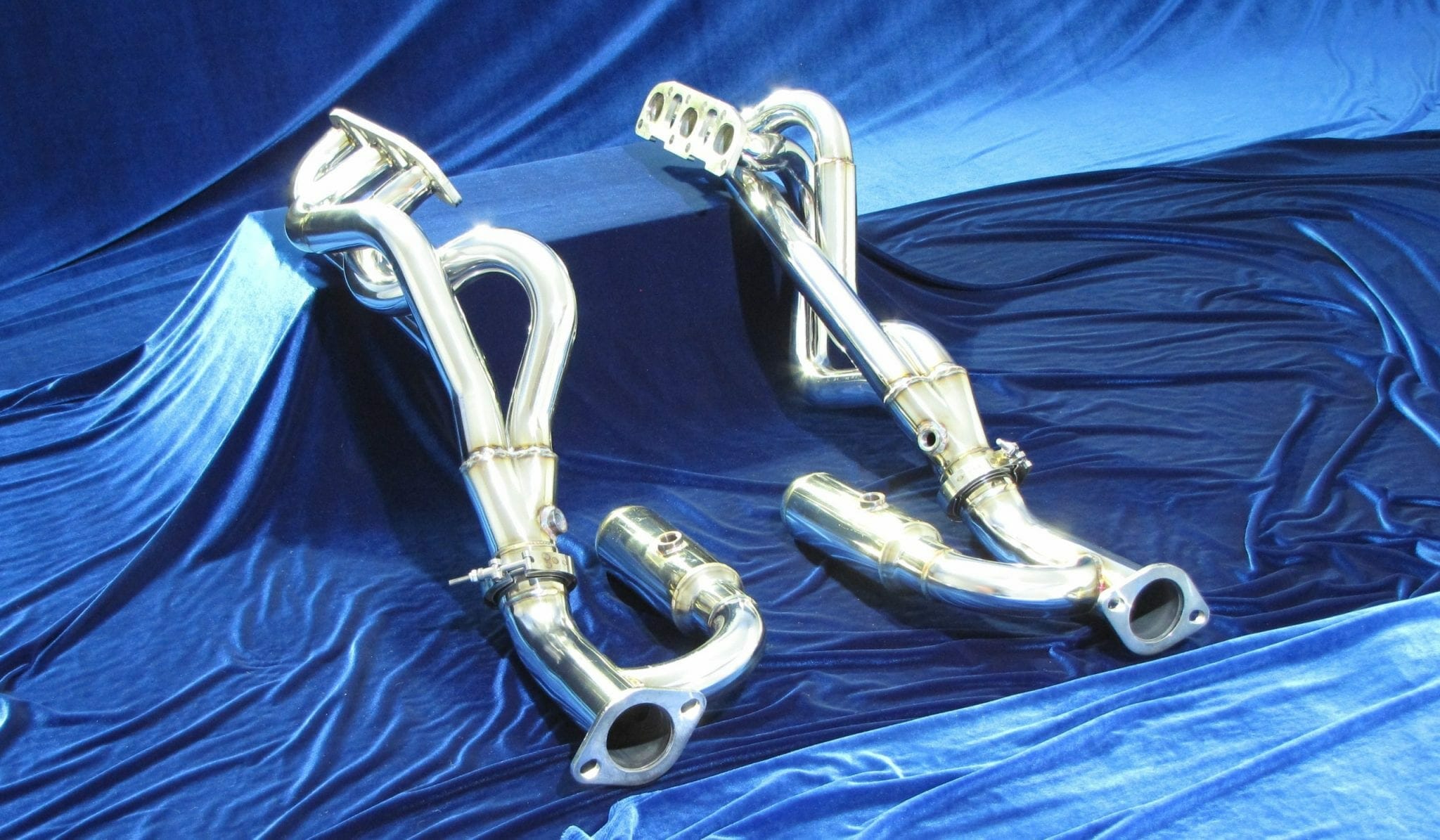
When an exhaust valve opens, a high-pressure pulse travels down the primary tube at the speed of sound. When this pulse reaches a change in pipe diameter, such as the collector, it reflects back toward the engine as a negative pressure wave. If the primary tube length is optimized, this negative wave arrives back at the exhaust valve exactly when it is open, creating a vacuum that "pulls" the remaining exhaust out of the cylinder. This is the heart of exhaust manifold pulse tuning, which allows for more efficient cylinder filling during the next intake stroke.
1.2.2 The Synergy Between Primary Tube Diameter and Harmonic Extraction
The diameter of the primary tubes dictates the speed at which the pressure pulse travels. If the diameter is too small, friction losses outweigh the benefits of velocity. Conversely, an oversized diameter causes the pressure wave to lose intensity and arrive too late to assist with scavenging. Achieving the perfect balance requires matching the pipe diameter to the engine’s specific RPM range, where the harmonic resonance of the tubing aligns with the engine's firing frequency.
1.2.3 Collector Design and Its Influence on Pulse Synchronization
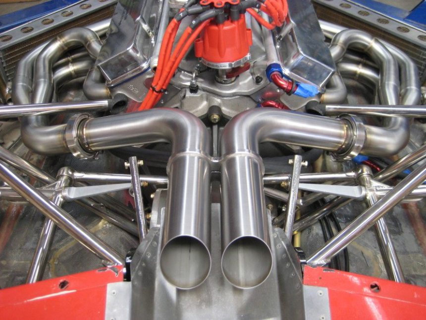
The collector acts as the junction where individual primary pulses meet. A high-quality collector is designed to manage the interference of these pulses so that they do not cancel each other out. By using a merge-style collector, designers can ensure that the transition is smooth, maintaining the kinetic energy of the individual pulses as they merge into the main exhaust system.
1.3 Material and Construction Considerations for Flow Efficiency
1.3.1 Comparing Mandrel-Bent versus Crush-Bent Tubing
The manufacturing method of the piping dictates its internal flow characteristics. Crush-bending—the cheaper, common method—often creates significant restriction at the bends, effectively reducing the diameter and creating a bottleneck. Mandrel-bending, however, maintains a constant internal diameter throughout the bend by using an internal support rod. For any performance-oriented application, mandrel-bent tubing is the gold standard for preserving velocity.
1.3.2 Surface Finish and Internal Coating Effects on Skin Friction
Internal skin friction plays a surprising role in high-RPM performance. Rough surfaces, such as those found inside standard factory piping or poor-quality welds, create a boundary layer of slower-moving gas. Many professional builders now use ceramic internal coatings or high-polished surfaces to reduce this friction, allowing the exhaust gas to slide through the system with minimal drag.
1.3.3 Thermal Management Strategies to Maintain Gas Velocity
Beyond just keeping the gases hot, managing the thermal expansion of the metal is vital. As the exhaust system reaches operating temperatures, the metal expands, which can alter the internal volume and pulse timing. Advanced thermal management, including external heat wraps or shielding, helps keep the system within a stable operating window, ensuring that the velocity tuning remains consistent across both cold starts and sustained high-load track usage.
2. Practical Application and Troubleshooting in Exhaust System Tuning
2.1 Matching Hardware to Engine Operating Profiles
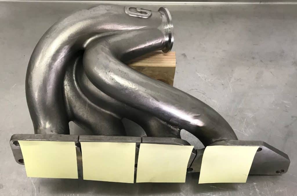
Optimizing your system starts with understanding that there is no universal diameter that works for every engine. The goal is to maintain sufficient gas velocity to support efficient scavenging while ensuring the flow path is large enough to prevent unnecessary restriction at the engine’s peak power point.
2.1.1 Calculating Optimal Tube Dimensions for Low-RPM Torque
For street-driven engines, maximizing low-end torque is usually the priority. Smaller diameter primary tubes increase gas velocity, which enhances the inertial effects of the exhaust pulse. This higher velocity ensures that the pressure waves effectively pull the next charge of air and fuel into the cylinder during valve overlap. When selecting your piping, err on the side of a slightly smaller diameter to keep the "slug" of exhaust gas moving quickly at lower engine speeds.
2.1.2 High-RPM Power Optimization and Velocity Maintenance
As you move toward high-RPM applications, the volume of exhaust gas increases dramatically. If your piping is too restrictive, backpressure will rise, forcing the engine to work harder to push gases out, effectively choking your power output. At this stage, you must balance the need for high-velocity pulses with the sheer capacity required to move a higher volume of air. Using [url=https://jasma.org/exhaust-gas-velocity-vs-torque-mapping-optimizing-flow.html]exhaust gas velocity vs torque mapping[/url] can provide the data necessary to find the "sweet spot" where your engine breathes freely without losing the scavenging benefits of a well-tuned system.
2.1.3 Avoiding the Excessive Diameter Syndrome
A common mistake enthusiasts make is installing the largest exhaust piping available. While a massive diameter may seem like the best path to performance, it often backfires. Excessive diameter causes the exhaust gases to lose heat and velocity rapidly. As velocity drops, the scavenging effect disappears, and the exhaust pulses become lazy and disorganized, leading to a noticeable loss in throttle response and low-end torque.
2.1.4 Balancing Backpressure Requirements for Specific Engine Types
Naturally aspirated engines rely heavily on precision-tuned headers to create a vacuum effect at the exhaust valve. Conversely, forced induction engines operate under different principles; for these platforms, minimizing restrictions is often more beneficial than chasing specific pulse-tuning harmonics. Understanding how different engines respond to pressure changes is vital to choosing the right diameter for your specific setup.
2.2 Diagnostics and Advanced System Integration
Moving beyond basic hardware selection, modern tuning requires a methodical approach to identifying bottlenecks and ensuring the entire system works in harmony with the engine management suite.
2.2.1 Using Computational Fluid Dynamics for Prototyping
Engineers use Computational Fluid Dynamics (CFD) to visualize how gases travel through bends and collectors. For the average builder, this means prioritizing smooth, consistent transitions and avoiding sharp angles that create turbulence, which acts as a virtual restriction in your piping.
2.2.2 Diagnostic Testing to Identify Flow Bottlenecks
Pressure testing is the most effective way to identify inefficiencies. By installing pressure transducers at various points—such as before and after the catalytic converter or muffler—you can pinpoint exactly where the system is failing to maintain desired velocity.
2.2.3 Mitigating Acoustic Resonance and Exhaust Drone
High-velocity exhaust systems can often produce unwanted standing waves, commonly heard as drone. By adjusting pipe length or adding Helmholtz resonators, you can target specific frequencies to cancel out this drone without sacrificing flow performance.
2.2.4 The Impact of Velocity Changes on ECU Mapping and Air-Fuel Ratios
Any significant change in your exhaust system’s flow characteristics will alter the engine's volumetric efficiency. A more efficient exhaust often allows the engine to ingest more air, which may lean out the mixture. It is essential to monitor your air-fuel ratios and adjust your ECU mapping accordingly to prevent potential engine damage and ensure you are capturing the gains your new exhaust system provides.
Mastering automotive exhaust gas velocity optimization is more than a technical exercise; it is the art of balancing fluid dynamics with your engine’s specific breathing requirements. By focusing on the delicate equilibrium between pulse tuning and pipe diameter, you can effectively enhance your vehicle’s torque curve and throttle response without falling into the trap of over-sizing your exhaust components. Remember that velocity—not just volume—is the true engine of performance gains. Whether you are aiming for low-end grunt or sustained high-RPM horsepower, the key lies in maintaining efficient flow characteristics throughout the entire system, from the manifold collector to the muffler tip.
As you refine your setup, consider how individual components contribute to the system’s overall efficiency. Understanding the trade-offs between backpressure and scavenging is essential for long-term reliability and power delivery. For those looking to dive deeper into how your choice of hardware influences these dynamics, our guide on exhaust system backpressure effect on turbo spool and power offers critical insights for forced induction applications. Whether you are a weekend track enthusiast or a daily-driving gearhead, applying these engineering principles will help you extract the most potential from your engine. Take the time to measure, model, and test your configuration to ensure your exhaust system works in perfect harmony with your powerplant.