
When you are looking to squeeze every bit of efficiency out of your vehicle’s exhaust system, understanding the nuance of high-performance muffler internal perforation patterns is essential. While many enthusiasts focus solely on the outward aesthetics of a muffler or the diameter of the piping, the real engineering magic happens inside the canister. The way internal holes are shaped, spaced, and arranged directly dictates how your engine manages exhaust gas velocity, backpressure, and sound wave cancellation. Whether you are building a dedicated track car or fine-tuning a street-performance machine, selecting the right pattern is a delicate balance between optimizing flow and achieving the desired acoustic profile. In this guide, we explore the science behind these internal designs, helping you make informed decisions that align with your power goals and performance requirements. Understanding the principles of high-flow muffler internal design will empower you to transition from simple part replacement to true systems engineering, ensuring your exhaust setup delivers both power and reliability on the road or the track.
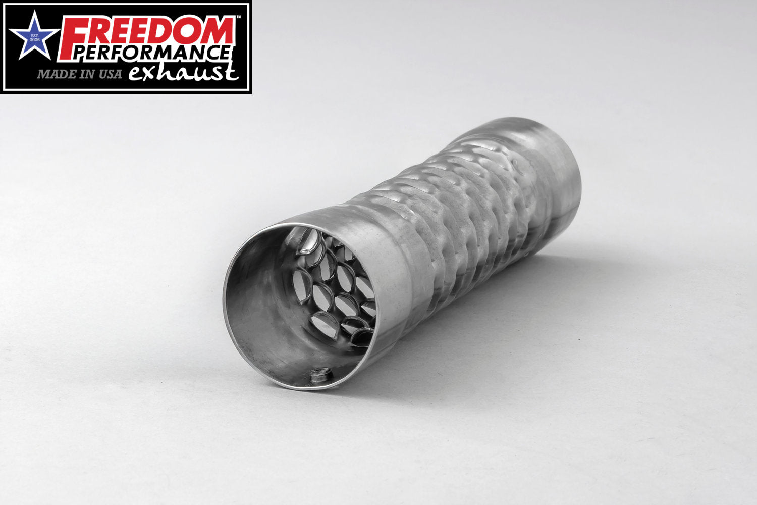
1. Engineering Principles of High-Performance Muffler Internal Perforation Patterns
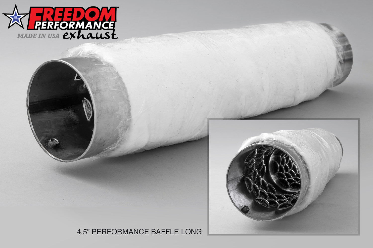
1.1 Geometric Influence on Flow Dynamics and Acoustic Tuning
1.1.1 Evaluating round versus slotted versus louvered hole shapes
The geometry of the perforations inside a core is not merely an aesthetic choice; it dictates the interaction between the exhaust gas and the surrounding sound-deadening materials. Round holes provide the most structural integrity and uniform flow, making them ideal for high-pressure, forced-induction applications where turbulence must be minimized. Slotted perforations, conversely, offer a higher open-area percentage, which can improve sound absorption coefficients by allowing more exhaust energy to penetrate the packing material. Louvered patterns are uniquely engineered to induce a specific flow directionality; by creating a slight scoop, they can encourage gas to exit the primary pipe into the absorption chamber, effectively managing noise while minimizing the typical performance bottlenecks found in restrictive baffles.
1.1.2 Calculating the critical open area percentage for engine efficiency
Achieving the right balance of performance exhaust flow dynamics requires precise calculations of the open-area percentage. If the density of the perforations is too low, the muffler acts as a bottleneck, creating backpressure that hampers engine output. If the density is too high, the structural rigidity of the core pipe is compromised, leading to vibration and potential failure under extreme exhaust gas temperatures. Engineers typically aim for an open area between 30% and 45% for street-performance applications. This range ensures that the muffler does not disrupt the primary exhaust pulse while still providing sufficient surface area for the acoustic dampening materials to capture and dissipate high-frequency noise.
1.1.3 Impact of staggered versus linear grid patterns on structural integrity
The arrangement of the holes—whether in a linear or staggered grid—significantly impacts the muffler's long-term durability. A linear pattern, while simpler to manufacture, can create continuous lines of weakness along the pipe, which are prone to stress fractures under thermal cycling. A staggered grid pattern is the industry standard for high-flow muffler internal design because it distributes the mechanical load more evenly across the material surface. By offsetting the perforations, the pipe maintains its hoop strength, preventing the core from deforming or "tin-canning" when subjected to the intense pressure pulses of a high-revving engine.
1.2 Physics of Pulse Management and Scavenging
1.2.1 Mechanics of converting exhaust pressure pulses into thermal dissipation
High-performance mufflers function by turning kinetic energy from exhaust pressure pulses into heat. When the pulse hits the perforation pattern, a portion of the wave is forced through the holes into the surrounding packing cavity. This physical redirection breaks down the amplitude of the sound wave. As the gas molecules vibrate through the packing fibers, friction converts that acoustic energy into thermal energy, which is then dissipated through the muffler casing. This process effectively reduces the decibel level without the massive flow restriction of traditional chambered designs.
1.2.2 Relationship between hole diameter and high-RPM scavenging efficiency
At high RPMs, the speed of the exhaust gas is critical for maintaining efficient scavenging. Larger hole diameters reduce the sheer surface area that creates drag, helping to maintain high exhaust gas velocity. However, if the holes are too large, they can cause the exhaust gas to "puff" out and re-enter the pipe sporadically, creating turbulence that disrupts the scavenging effect. Selecting the optimal hole diameter involves matching the muffler core size to the engine displacement, ensuring that the pressure waves pull the next charge of air-fuel mixture into the combustion chamber effectively.
1.2.3 Targeting specific resonant frequencies for unwanted drone elimination
Managing exhaust sound resonance frequency cancellation relies on the interplay between perforation density and the length of the muffler core. By precisely spacing the perforations, engineers can create a tuned Helmholtz resonator effect within the packing material. This allows the system to target and cancel out the specific frequencies that cause cabin drone during highway cruising. By adjusting the hole pitch and the diameter of the perforated section, it is possible to maintain a deep, aggressive exhaust note under acceleration while significantly quieting the system at steady-state engine speeds.
2. Advanced Design and Integration Strategies for Custom Exhaust Fabrication
2.1 Matching Perforation Geometry to Engine and Application Requirements
2.1.1 Optimizing density for forced induction versus naturally aspirated systems
The core philosophy when designing high-performance muffler internal perforation patterns lies in balancing gas velocity with acoustic control. For forced induction engines, the priority is minimizing backpressure to allow the turbocharger or supercharger to operate within its most efficient map. Here, lower perforation density is often preferred to maintain laminar flow and prevent the pressure pulses from bleeding too aggressively into the packing material, which can cause premature heat soak. Conversely, naturally aspirated engines rely heavily on scavenging effects. A higher density of perforations helps in managing pulse waves to optimize exhaust gas velocity, ensuring that the pressure drop across the muffler complements the engine’s valve overlap and RPM range.
2.1.2 Determining core diameter sizing based on engine displacement and volume
Core diameter is the foundation of your flow equation. If the core is too small, the muffler acts as a bottleneck; if it is too large, you lose the gas velocity required for effective scavenging. As a general rule, the internal core diameter should scale proportionally with engine displacement and target peak horsepower. Utilizing a high-flow muffler internal design ensures that the cross-sectional area of the perforations supports the total volume of exhaust gas moving through the system at high RPM. For street-driven vehicles, tapering the core diameter slightly can help maintain torque at lower RPMs without sacrificing top-end breathing.
2.1.3 Street performance balance versus dedicated track flow maximization
The distinction between street and track fabrication centers on the trade-off between decibel suppression and flow efficiency. Street-oriented designs often utilize complex louvered patterns that encourage sound absorption through turbulence, which is excellent for drone elimination but slightly inhibits raw flow. Dedicated track systems move toward straight-through designs with simple, clean-cut circular perforations. These patterns minimize gas impingement, allowing for maximum mass flow rate. When fabricating for the street, it is crucial to prioritize resonant frequency management, as consistent drone can make a high-performance system unbearable for daily use.
2.2 Material Compatibility and Long-term Performance Durability
2.2.1 Interaction between hole sizing and packing material fiber thickness
The relationship between your perforation hole diameter and the chosen packing material is critical for preventing material blow-out. Large, aggressive perforations can lead to the exhaustion of sound-deadening fibers if the packing material is not robust enough to bridge the gap. When designing custom internals, always match the fiber diameter of your glass or basalt wool to the hole size. If using large-diameter slots, consider an intermediate layer of stainless steel mesh to prevent the packing material from being sucked through the perforations during high-load scenarios.
2.2.2 Preventing pattern deformation in high exhaust gas temperature environments
Exhaust gas temperatures (EGTs) in high-performance applications can easily push the limits of thin-gauge stainless steel. If the perforation pattern is too dense, the structural integrity of the inner core pipe is compromised, leading to warping or "bellowing" under thermal expansion. To mitigate this, engineers often utilize a grid layout with sufficient "bridge" space between holes. Maintaining structural mass between perforations is essential to ensure that the internal tube remains rigid even when glowing red-hot under sustained track use.
2.2.3 Mitigating vibration-induced material fatigue through calculated pitch spacing
Vibration is the silent killer of custom exhaust components. By calculating the pitch spacing of the perforation pattern, you can shift the natural resonant frequency of the core tube away from the engine’s operating harmonics. A calculated, uneven, or staggered pitch spacing can help dampen the mechanical vibrations transferred through the exhaust system, preventing the initiation of micro-cracks around the edges of the perforations. This precision in design not only improves the longevity of the muffler internals but also contributes to a cleaner, more refined exhaust note that avoids the raspy metallic character often associated with poorly executed custom fabrication.
Mastering high-performance muffler internal perforation patterns is more than just an exercise in fabrication; it is a critical balance between exhaust flow dynamics and acoustic refinement. By carefully selecting your hole geometry, density, and layout, you can effectively manage backpressure to unlock hidden horsepower while simultaneously mitigating the unwanted drone that often plagues modified exhaust systems. Whether you are building for the track or the street, the physics of gas velocity and resonance frequency cancellation remains the cornerstone of any successful high-flow design.
As you refine your setup, remember that structural integrity is just as vital as performance gains. Proper material selection and attention to vibration-induced fatigue ensure your custom exhaust will stand the test of time under high-heat conditions. If you are aiming for a setup that is both efficient and legally conscious, we recommend reviewing our guide on noise control standards for modified vehicles to ensure your configuration meets necessary regulatory requirements. By combining these engineering principles with a disciplined approach to maintenance and compliance, you can achieve a sophisticated, high-performance exhaust system that truly performs as well as it sounds.