
In the world of high-performance automotive engineering, managing the intense thermal loads generated by a combustion engine is as critical as power delivery itself. Exhaust system thermal fatigue analysis is a vital process for engineers and enthusiasts alike, as it helps identify how repeated heating and cooling cycles compromise structural integrity over time. When an exhaust manifold or piping assembly reaches extreme operating temperatures, the metal undergoes significant expansion; as it cools, the resulting contraction places immense strain on welds, flanges, and brackets.
Left unmanaged, these thermal stresses lead to micro-crack propagation, eventual material failure, and leaks that ruin backpressure profiles. By understanding the underlying physics of material degradation and implementing proper performance exhaust thermal management, you can significantly extend the lifespan of your components. In this guide, we will break down the methodologies for analyzing these thermal loads and offer actionable strategies to prevent premature failure, ensuring your exhaust system maintains its durability and performance under the most demanding conditions.
1. Advanced Methodologies for Exhaust System Thermal Fatigue Analysis
1.1 Physics of Failure and Thermal Cycling Dynamics
1.1.1 Mechanisms of Micro-crack Initiation and Propagation
Thermal fatigue in exhaust systems begins at the microscopic level. As temperatures cycle from ambient to extreme operational highs, the material undergoes repeated expansion and contraction. Stress concentrators, such as weld toes, tight radii in manifold runners, or irregularities in surface finish, become the focal points for micro-crack initiation. Under cyclic thermal loading, these cracks propagate through the crystalline structure of the alloy. Once a crack reaches a critical length, the structural integrity of the component is compromised, often manifesting as a leak or, in severe cases, catastrophic separation of exhaust sections.
1.1.2 Distinguishing Thermal Shock from Long-term Creep Deformation
Understanding the difference between thermal shock and creep is essential for accurate diagnostics. Thermal shock occurs when rapid, localized temperature changes—such as cold startup followed by immediate wide-open throttle—induce severe internal stresses that exceed the material's yield strength. Conversely, creep is a time-dependent, permanent deformation that occurs under sustained high-temperature load, even when stresses are below the yield point. Identifying whether failure originated from a sudden event or a prolonged duty cycle is a vital part of professional exhaust system durability testing, as it dictates whether the fix requires thermal management or a change in alloy composition.
1.1.3 Impact of Temperature Gradients on Material Expansion and Contraction
Exhaust systems rarely heat uniformly. Complex geometries often create temperature gradients where one portion of the pipe is significantly hotter than the adjacent section, leading to differential thermal expansion. This creates internal tension and compression forces that act as the primary drivers of fatigue. By managing these gradients, engineers can prevent the "fighting" between rigidly connected components that leads to premature stress-related failures.
1.2 Predictive Modeling and Computational Engineering
1.2.1 Leveraging Computational Fluid Dynamics for Thermal Field Mapping
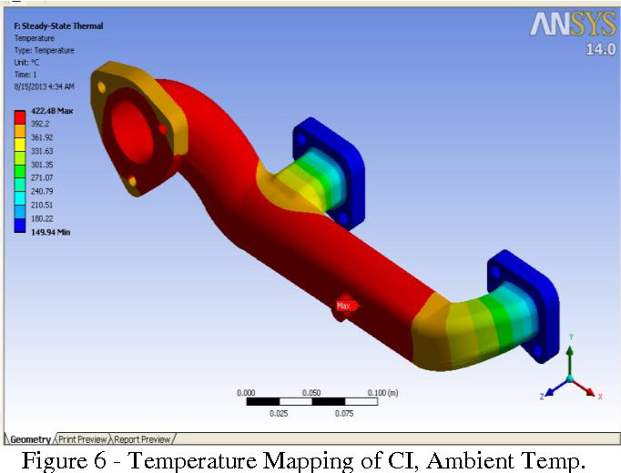
Modern exhaust design relies on Computational Fluid Dynamics (CFD) to predict thermal distribution before a prototype is even built. CFD allows engineers to visualize gas flow patterns and identify "hot spots" where heat buildup will be most severe. By mapping the thermal field, designers can preemptively adjust pipe wall thickness or routing to ensure more uniform heat dissipation.
1.2.2 Implementing Finite Element Analysis for Structural Stress Correlation
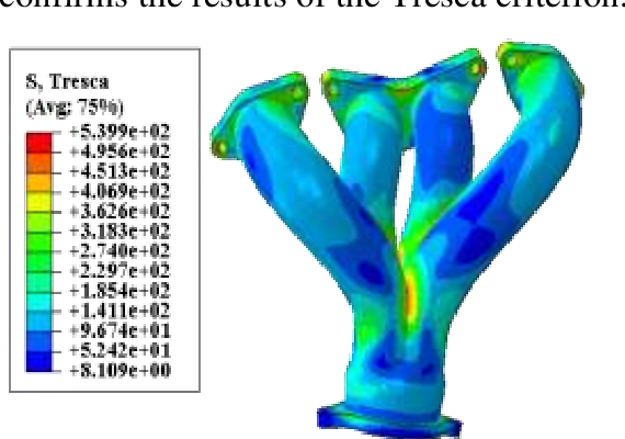
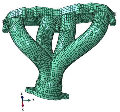
Finite Element Analysis (FEA) translates those thermal maps into structural stress data. By simulating the physical expansion of the exhaust system under heat, FEA highlights exactly where mounting points, flanges, and welds will face the highest strain. This predictive modeling is essential for identifying potential fatigue points during the design phase, allowing for geometry optimization before physical manufacturing begins.
1.2.3 Utilizing Rainflow-counting Algorithms for Transient Cycle Prediction
To predict how a system will perform over its entire lifespan, engineers utilize rainflow-counting algorithms. This statistical method breaks down complex, real-world transient thermal cycles—like stop-and-go city driving versus sustained highway cruising—into manageable stress events. By quantifying the frequency and amplitude of these thermal cycles, developers can accurately estimate the fatigue life of high-output components.
1.2.4 Standardizing Experimental Validation via Accelerated Life Testing
Computational models must be validated through rigorous experimental testing. Accelerated Life Testing (ALT) mimics years of thermal stress in a compressed timeframe by cycling the exhaust system through extreme temperature fluctuations. This process ensures that the theoretical models match reality, providing a definitive benchmark for material reliability and long-term structural endurance.
2. Prevention, Mitigation, and Design Strategies for Exhaust System Thermal Fatigue Analysis
2.1 Engineering Solutions for Structural Durability
When addressing the long-term integrity of an exhaust system, the primary engineering goal is to decouple the rigid engine block from the heat-stressed exhaust tubing. The most effective way to manage these forces is by optimizing component geometry.
2.1.1 Optimizing Component Geometry with Bellows and Sliding Joints
Thermal expansion is inevitable in high-performance exhaust systems. Rigid mounting points act as anchors that force the material to buckle or crack under stress. Incorporating stainless steel bellows or flexible decouplers allows the exhaust system to expand and contract linearly without transferring these mechanical loads to the manifold or turbocharger housing. Sliding slip-joints also provide a reliable way to accommodate axial movement in longer exhaust runs, effectively neutralizing the stress that leads to crack initiation at weld zones.
2.1.2 Mitigating Interface Stress through Thermal Expansion Coefficient Matching
One common failure mode occurs when two different metals with varying thermal expansion rates are joined together. When one section of the system expands faster than the other, it creates localized strain at the interface. Engineers combat this by utilizing materials with similar expansion coefficients at flanges and junctions. For those modifying their setups, it is crucial to understand that a proper performance exhaust thermal management strategy considers the specific alloy composition of each component to ensure the entire system grows and shrinks uniformly during heat cycles.
2.1.3 Advanced Material Selection Including Inconel and Specialized Cast Alloys
Standard 304 stainless steel is common, but it can reach its endurance limit in high-output environments. Moving toward high-nickel alloys like Inconel provides superior creep resistance and structural stability at temperatures that would cause standard steel to become ductile and fail. While more expensive, these materials are often necessary for extreme applications where the thermal fatigue analysis predicts high stress concentrations, ensuring the system survives repeated, rapid heating and cooling cycles.
2.2 Operational Management and Maintenance Best Practices
Design is only half the battle; how you manage the system during daily operation determines its lifespan.
2.2.1 Evaluating the Role of High-temperature Coatings and Heat Shielding
Effective thermal shielding materials for high-output exhaust systems, such as ceramic coatings or specialized thermal wraps, serve a dual purpose. They keep heat energy contained within the gas stream—which helps exhaust velocity—while simultaneously lowering the skin temperature of the exhaust components. By maintaining a more stable, lower surface temperature, these coatings significantly reduce the thermal gradient, preventing the rapid metal fatigue that stems from excessive heat soak.
2.2.2 Mitigating Thermal Shock via Engine Management Calibration
Rapid changes in exhaust gas temperature (EGT) trigger thermal shock, which causes micro-cracks to propagate quickly. Modern engine management systems can be calibrated to include warm-up enrichment cycles that bring the exhaust system to operating temperature more gradually. Avoiding aggressive wide-open throttle pulls immediately after a cold start is a simple but vital operational habit that prevents premature material degradation.
2.2.3 Diagnostics and Non-destructive Testing of Weld Joints and Flanges
Even the best-engineered systems require periodic inspection. Using non-destructive testing (NDT) methods like dye-penetrant inspection allows for the early detection of stress fractures in weld beads before they result in a full fatigue failure. Regularly checking for loose fasteners and excessive mechanical vibration is also essential, as vibration acts as a catalyst for fatigue crack propagation, turning minor thermal stresses into catastrophic structural breaks.
Mastering exhaust system thermal fatigue analysis is more than an engineering exercise; it is the cornerstone of building long-term durability in high-performance automotive platforms. By understanding the interplay between thermal cycling, material selection, and structural stress, you can effectively predict failure modes before they compromise your vehicle’s integrity. Moving beyond simple thermal management, this analytical approach—incorporating Finite Element Analysis and rigorous material validation—ensures that your exhaust system can handle the intense demands of modern high-output engines.
Preventative strategies, ranging from the integration of flexible bellows to the use of advanced heat shielding, are essential for mitigating the inevitable stresses of high-temperature operation. As you look to optimize your own setup, remember that consistent maintenance and periodic inspection are just as vital as the initial design. For those looking to dive deeper into system longevity, our exhaust maintenance and cleaning tips for longevity provide a practical roadmap to help you protect your investment. By applying these engineering insights and proactive care, you can ensure your exhaust system remains reliable, efficient, and performance-ready, regardless of the thermal environment it faces.